
The System Overview shows the Terrier SC communications products, the SPTs connect via Signalling Paths to our Receiver applications, which run on servers in the monitoring centre. The Config Server application directs the SPTs to the appropriate Receiver and is a part of our management infrastructure which includes a Support Platform that interacts with our applications.
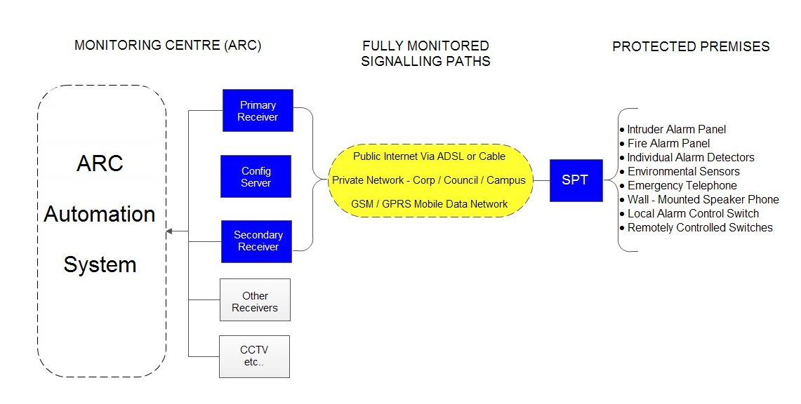
Looking in more detail, we will start with the SPT:
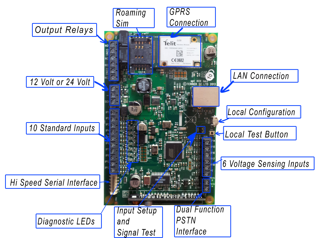
The SPT – supervised premises transceiver – has inputs and outputs. The inputs are interfaces for the on-site equipment to capture alarms which are turned into messages that go to the outputs and are transmitted along a signalling path. The installer is provided with a number of in-built tools and diagnostics to ensure the SPT is fully operational.
SPT INPUTS for site equipment connections
“Pin Inputs” – 16 of these are standard and each can accept the signals from a wide range of equipment that indicates an alarm condition by changing a relay output or a voltage ouput. So each pin input will accept two states that are in a Normal state or in an Alarm state and the SPT will generate an alarm message whenever a pin input changes state.
“PSTN Input” – Two connections that mimic the telephone line. It provides ~50v dc and a telephone or a Digicom transmitter in an alarm system will get dial tone when it goes Off-Hook. It accepts DTMF dial-strings and if the SPT has been programmed for alarm handling, it will accpet an alarm system’s Fast Format, Contact ID or SIA Format alarm message. If the SPT has been programmed as an emergency telephone, it will make a GSM telephone call.
“Serial Input” – Ten-way connector with a TTL level RS232 interface. Currently supporting an alarm panel signalling protocol with further development expected.
SPT OUTPUTS for connecting to the Monitoring Centre
“LAN” – an Ethernet connector to accept a cable for access to the premises Local Area Network and onward via the Internet.
“GPRS” – an antenna to access a mobile data network for access to the Internet.
SPT TOOLS and DIAGNOSTICS for the installing or maintenance engineer
“Test Button” – causes a Test Alarm to be sent to the Monitoring Centre
“Learn Input” – two functions. One is to force the SPT to initialise the Pin Inputs. The second is to change the mode of the Diagnostic LEDs to show the GPRS Signal Strength
“Diagnostic LEDs” – in normal operation will show the status of the SPT’sconnections to the Monitoring Centre. As mentioned above, the LEDs will also show the GPRS Singal strength.
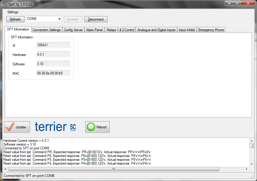 “SptCfg Application” – a software application for an installer to locally program the SPT via its USB connection.
The IP Alarm Receiver or Receiving Centre Transceiver (RCT)
The RCT also has inputs and outputs. Its inputs are from the LAN/WAN/Internet allowing SPTs to connect to it and the output is to the Alarm Automation system used by the Monitoring Centre.
The RCT passes alarm messages from the SPTs to the Monitoring Centre’s Alarm Automation system. monitors all connections and reports any that have failed and provides Users with detailed information via the Alarm Receiving Centre User Interface (ARCUI).
In the ARCUI, the user has an overview of all SPT connections which show their status…
.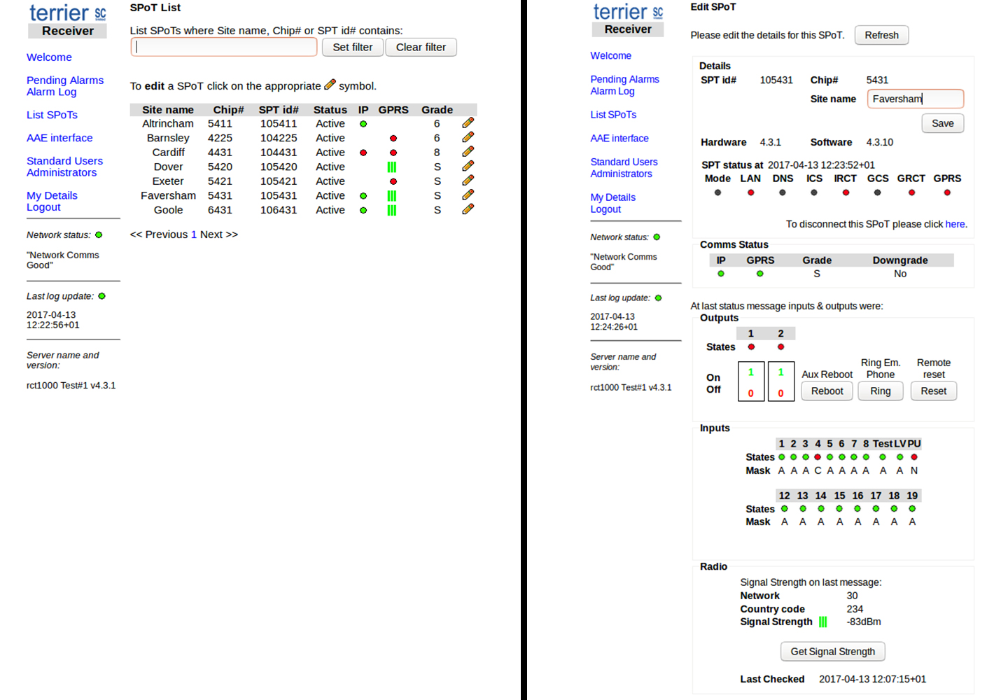 ..and can look at the detail for an individual connection and send control signals.
Management Infrastrucure
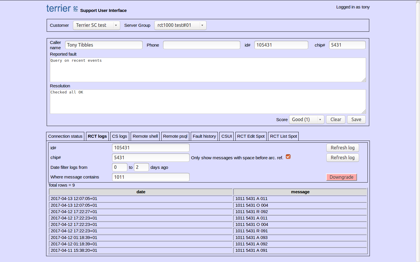 The Support Platform allows us to respond to calls from customers and view the SPT connections, their messages and give advice on any problems that are being experienced.
Recent Comments